MIL-C-48582B (AR)
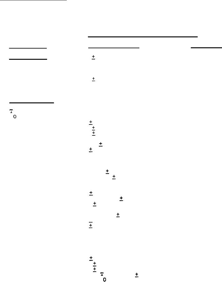
TABLE II.
Input and output characteristics
TERMINALS
CHARACTERISTIC CS
REQUIREMENT
P1-30,31,32(+)
5.00
0.25 Vdc regulated,
Input Power
P1-24,25,26
AC ripple not greater than
(Ret. )
50mvp-p, capacity 500ma.
P1-9,10,11(-)
-5.2
0.1 Vdc regulated,
P1-24,25,26
AC ripple not greater than
(Ret.)
50mvp-p, capacity 1.5A.
Input Signals
As required
Positive pulse from O to
(Sec. Fig. 4)
4.0
1.0 Vdc, width of
0.1 sect PRF of
0.79
0.2 KHz.
20.0
120MHz
1KHz sine wave,
J1
Signal #1
700
100mvp-p into 50 ohm
(Clock pulse)
load.
P1-41, P1-39
50% square wave, from
Signal #2
O to 4.0
1.0 vdc,
& P1-24 (Ret.)
(Count-Up,
PRF of 250
2 Hz.
Count Down)
Target Clear
Positive pulse from O to
P1-19
1.0 Vdc, width of
4.0
P1-25 (Ret.)
0.2 us and
between 15.8
50.0
0.5 us depending on
Target Overflow output pulse,
PRF of 20.0
0.2 KHz on for
8.2 + 0.1 sec. and off for
8.2
0.1 sec. Positive going
edge of Target Clear pulse is
coincident with negative going
edge of Target Overflow pulse.
Positive pulse from O to
Strobe
P1-33
4.0
1.0 Vdc, width of
P1-25 (Ret.)
0.10 us, PRF of
0.79
20.0
0.2 KHz, delayed from
system
by 42.0
5.2 US.
For Parts Inquires call Parts Hangar, Inc (727) 493-0744
© Copyright 2015 Integrated Publishing, Inc.
A Service Disabled Veteran Owned Small Business