MIL-C-60898/9 (MU)
Connect POWER SUPPLIES, Items 1 and 2 of 4.4.1,1, for
and
0.1 vdc,
respectively,
as shown in
-22.0
Figure 1 with their return leads connected to pin 28.
During
subsequent tests, measure all voltages referenced to pin 28
using the DIGITAL VOLT-OHMMETER, Item 6 of 4.4.1.1.
4.5,2.2
Pin
19
output Measure the d-c voltage at pin 19;
verify
conformance
with
3.4.2.
Measure the d-c voltage at pin 23;
4.5.2.3 Pin 23 output.
Increase the POWER SUPPLY,
verify conformance with
3.4.3,
Item 1 of 4,4.1.1, voltage to 28,0
0,1 vdc and again verify
conformance with 3.4.3.
4,5.2.4 Pin 9 output. Set POWER SUPPLY, Item 3 of 4.4.1.1, to
Connect the negative output of the supply to pin 12
1.25 vdc.
and the positive terminal-to pin 28". Verify that the voltage
on pin 9 is -21,0
1,0 vdc.
Readjust the POWER SUPPLY to
Verify that the voltage on pin 9 is -0.3
0.2 vdc.
1.55 vdc.
Measure the d-c voltage on pin 17.
4.5.2.5 Pin 17 output.
0.5 vdc. Connect the PULSE
Verify that the voltage is 21.0
Con-
GENERATOR, Item 4 of 4.4.1.1, between pin 20(+) and pin 28.
nect the OSCILLOSCOPE, Item 5 of 4.4.1.1, vertical input be-
tween pin 20(+) and pin 28. Set up the PULSE GENERATOR to produce
Verify that the voltage on pin 17 remains
the pulse of Figure 2.
Disconnect the PULSE GENERATOR and apply
0.5 vdc.
at 21.0
Using the POWER
0.1 vdc between pin 20(+) and pin 28.
22.0
SUPPLY, Item 3 of 4.4,1.1, verify that the voltage on pin 17 is
0.4 Vdc,
+1.2
Remove POWER SUPPLY, Item 3, and verify that the
voltage on pin 17 remains at +1.2
0.4 vdc.
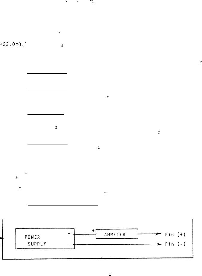
Connect the AMMETER, Item 7
4.5.2.6 Diodes reverse current,
and POWER SUPPLY, Item 3 of 4.4.1.1, per Figure 3 and apply the
leads to each set of pins of Table I.
Figure 3
with the "POWER-SUPPLY SET AT 28.0 0.1 vdc, verify that the
AMMETER reads 0,02 MILLIAMPERE or less for each connection of
Table I.
8
For Parts Inquires call Parts Hangar, Inc (727) 493-0744
© Copyright 2015 Integrated Publishing, Inc.
A Service Disabled Veteran Owned Small Business