MIL-C-60898/4(MU)
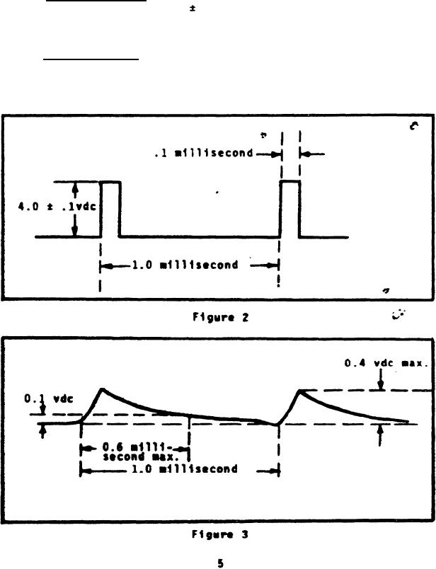
3.4.4 Capacitor C1.
With the signal shown in Figure 2
applied through a 100 ohm
10 percent resistor, between pin
25 (+) and pin 28, the voltage out between pin 25 (+) and pin
28 shall be l s shown in Figure 3.
3.4.5 Capacitor C2. With the signal shown in Figure 2 applied
through a 100 ohm ± 10 percent resistor, between pin 13 (+) and
pin 1, the voltage out between pin 13 (+) and pin-l shall be as
shown in Figure 3.
For Parts Inquires call Parts Hangar, Inc (727) 493-0744
© Copyright 2015 Integrated Publishing, Inc.
A Service Disabled Veteran Owned Small Business