MIL-C-60898/11(MU)
4.5.2.1.3 Pin 9 output. Connect POWER SUPPLY, item 1 of
4.4 1.1 in series with
the 5 kilohm resistor of ASSORTED
COMPONENTS, item 6 of 4.4.1.1 as shown in Figure 1.
Apply
the series combination between pin 6 and pin 9 and then
between pin 12 and pin 1.
Repeat for both polarities.
Using
the DVM, item 4 of 4.4.1.1 measure the voltage between pin 9
and pin 6 or pin 12 for each of the four connections to verify
the requirements of 3.4.1.3.
4.5.2.1.4
Diodes, reverse current.
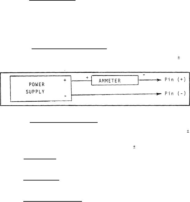
Connect the AMMETER,
item 5, and POWER SUPPLY, item 7 of 4.4.l.l, as shown in
Figure 5.
Adjust the POWER SUPPLY for an output of 28.0
0.1 vdc and verify that the AMMETER indicates 0.02 ma or less
for each connection specified in 3.4.1.4.
Figure 5
Connect the AMMETER, item
4.5.2.1.5 Diodes, forward drop.
5, and POWER SUPPLY, item 7 of 4.4.1.1, as shown in Figure 5.
Adjust the POWER SUPPLY such that the AMMETER indicates 1.0
0.1 ampere.
Connect the AMMETER and POWER SUPPLY to the card
as specified in 3.4.3.
Verify, with the DIGITAL VOLTMETER,
item 6 of 4.4.1.1, that the voltage is 0.9
0.3 vdc.
4.5.2.2 Capacitor.
Using the CAPACITANCE BRIDGE, item 8 of
4.4.1.1, measure the capacitance between pin 27 and pin 1 to
verify conformance with 3.4.2.
Measure the resistance between the pins
4.5.2.3 Resistance.
specified in Table II with the DIGITAL VOLTMETER, item 4 of
4.4.1.1, to verify conformance with the requirements of 3.4.3.
Connect the ASSORTED COMPONENTS,
4.5.2.4 Pulse transformer.
item 6, and POWER SUPPLY, item 2 of 4.4.1.1, as shown in Figure
Connect the OSCILLOSCOPE, item 3 of 4.4.1.1, to pin 11 (+)
3.
Adjust the OSCILLOSCOPE to trigger on an internal
and pin 8 (-).
positive going signal.
Observe the trace on the OSCILLOSCOPE and
Verify that the waveform on the
place switch A in position 2.
OSCILLOSCOPE conforms to 3.4.4 and Figure 4.
8
For Parts Inquires call Parts Hangar, Inc (727) 493-0744
© Copyright 2015 Integrated Publishing, Inc.
A Service Disabled Veteran Owned Small Business