MIL-T-50332A (AR)
3.5.2.5 2A2 OVERLOAD indicator (S3)
3.5.2.5.1 High voltage power supply overload. When 28 Vdc is
present between J3-1 and J3- 16, HIGH VOLTAGE POWER SUPPLY legend
of S3 shall be illuminated.
3.5.2.5.2 Modulator overload. When 28 Vdc is present between
J3-3 and J3-16, MODULATOR legend of S3 shall be illuminated.
3.5.2.6 2A2 OVERLOAD reset switch (S3). Between J3-2(+) and
J3-16 (Ret) 28 Vdc shall be present when S3 is actuated and con-
ditions are set in accordance with any of the following:
a.
3.5.2.2.2
b.
3.5.2.3.1
c.
3.5.2.3.2
3.5.2.7 TEST A/B switch (S10). Continuity exists between P2-C
and chassis ground when conditions are as stated in 3.5.2.3.2 and
S1O is in TEST A position.
3.5.2.8 VOLTAGE divider (A3) . With conditions as specified in
3.5.1.5.3, the output at. J6 shall be as follows:
i 1V at the most negative point.
a.
Minus 13.5
Plus 4.5 ±0.5V from leading edge baseline to
b.
most positive point, excluding overshoot.
Pulse shall be in accordance with Figure 2.
c.
3.5.2.9 EXTERNAL BEAM POWER SUPPLY test setup. With conditions
as specifie in 3.5.1.3.2, a shorting wire between TP6 and TP7,
and a shorting wire between J12-E and J12-A the output across a
100 ohm resistor inserted between J17-C and J12-B shall be as
follows:
a.
Ripple on peaks: less than IV peak to peak (not
including high frequency spikes).
Amplitude: 97.5 ± 5V
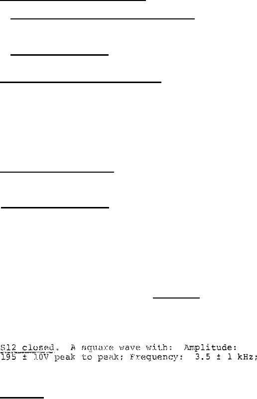
S12 open. Same as a. except:
b.
peak to peak.
c.
Output of TP2 (white) with respect to TP4 (black)
should read between NLT 9.OV to NMT 12.4 Vdc.
10
For Parts Inquires call Parts Hangar, Inc (727) 493-0744
© Copyright 2015 Integrated Publishing, Inc.
A Service Disabled Veteran Owned Small Business